Use cases
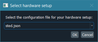
The first time the hardware control module is initialized, it will show a dialog to choose the hardware setup to be loaded. The user can change the setup option during execution in “Tools” -> “Pick hardware setup…” in the hardware control module’s menu bar.
Parallelized confocal and RESOLFT (MoNaLISA)
Here we explain how we implemented ImSwitch for MoNaLISA. In the article, you will find more information about the setup and how the data is reconstructed.
Configuration file and hardware specifications
For this microscope use case, we created the JSON file example_monalisa.json, located at /imswitch/_data/user_defaults/imcontrol_setups/example_monalisa.json
We chose a National Instruments Data Acquisition (NIDAQ) card for managing the synchronization of the devices.
In the JSON file, two cameras are specified for two-color imaging: Green and Red.
Both cameras are Hamamatsu, so they use HamamatsuManager. All the required camera properties are defined there,
like the DAQ digital line for external triggering, readout speed, exposure time, field of view, etc.
There are five lasers in this setup, we use acousto-optic modulators (AOM) connected to the DAQ to control some of them,
and others need the vendor interface as well, in this case Cobolt. The specific manager is defined for each type, LantzLaserManager or NidaqLaserManager, (see Hardware Control Configuration).
We use a X-Y-Z stage that we control through the DAQ as well, so the axes are defined as positioners using NidaqPositionerManager. The analog lines and conversion factors are specified as well.
The modules that will create the signals for the scan are BetaStageScanDesigner for the Stage, and BetaTTLCycleDesigner for the instrument synchronization.
Other config parameters related to scanning, regions of interest (ROI) and a list of widgets to be loaded are added in this file.
Hardware control module
This module is useful to control the hardware and screen the sample using widefield or our other patterns. We have provided a more detailed explanation of the GUI here. To record a super-resolution image the user sets the camera to external-trigger mode and inserts the scan pulse scheme. The scanning module synchronizes the different instruments through the DAQ, and the raw data is displayed in the liveview.
The user can choose to save the raw data either in disk (hdf5) or RAM (or both) using the Recorder widget. So, for example, we program our scan and then click “Scan Once” in REC to start our acquisition. The metadata is also saved in the hdf5 and can be reloaded from the toolbar. It contains all the scanning pulses and hardware parameters related to the experiment.
GUI while using two-color widefield:
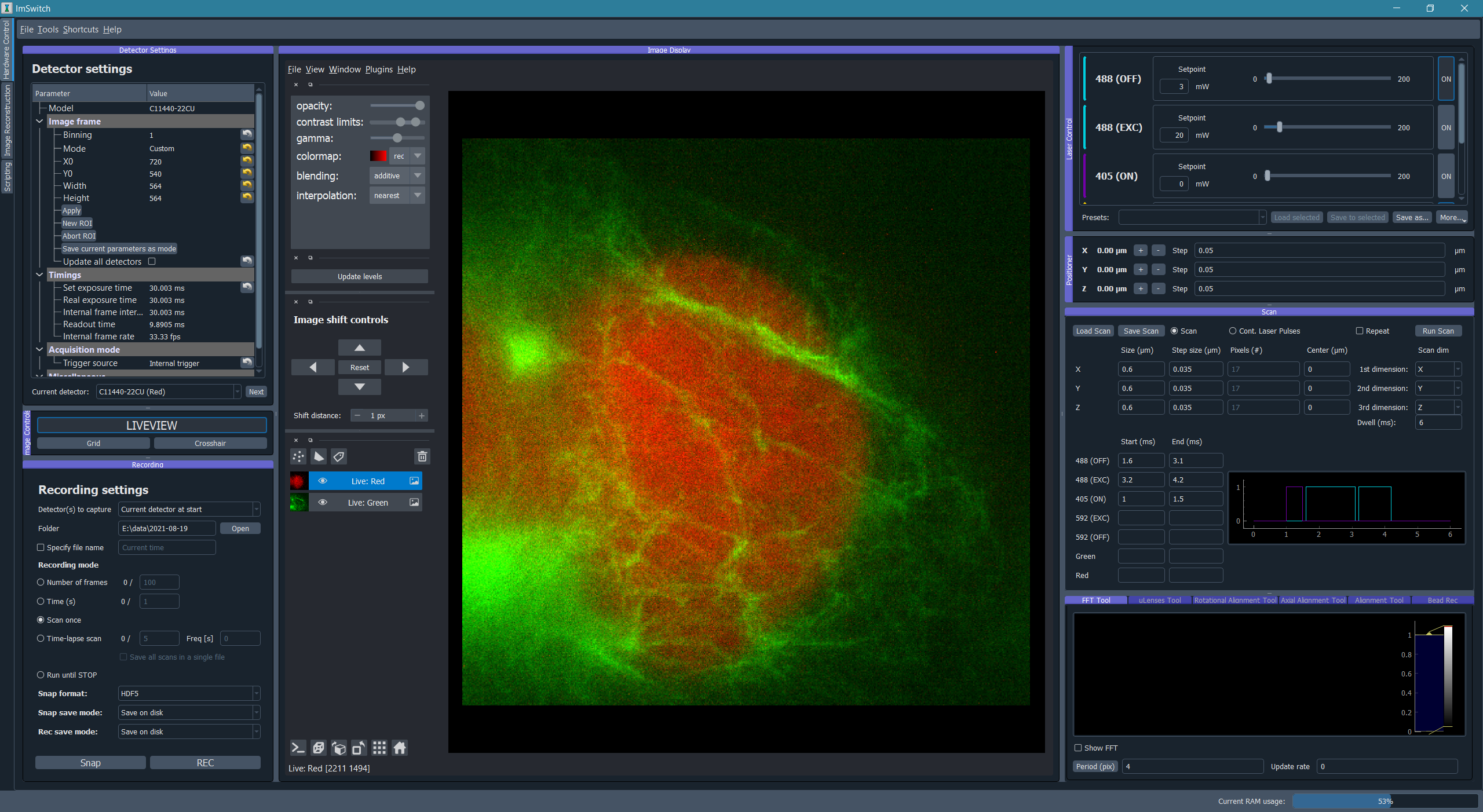
Image processing module for image reconstruction
The raw data can be either manually loaded into the reconstruction module or automatically retreived from the scanning if selected in the Recording widget. The user can further analyze the data using Napari image viewer. In this module we use our custom-designed DLLs for reconstruction, since this is a rather specific type of algorithm for our method. But the idea is that different microscope techniques implement their own modules as well. “Multidata management” stacks all the data incomming from the hardware control module.
The Image processing module is illustrated in the following image:

Point-scanning confocal and STED
Here we explain how we implemented ImSwitch for a custom-built STED setup in the lab, previously controlled by a combination of closed-source software (image acquisition) and purpose-built software (hardware control). In the article, you will find more information about the setup, what hardware it contains, and the type of image acquisition we want to perform.
Configuration file and hardware specifications
For this microscope use case, we created the JSON file example_sted.json, located at /imswitch/_data/user_defaults/imcontrol_setups/example_sted.json
We chose a National Instruments Data Acquisition (NIDAQ) card for managing the synchronization of the devices and image acquisition.
In the JSON file, two photon-counting point detectors (APD) are specified for two-color imaging: APDGreen and APDRed.
These do not need any specific hardware control, but instead are read entirely through the Nidaq.
Additionally two cameras are specified: one for widefield, for having an overview of the sample, and one for the focus lock, as described in detail in the cited article.
Both cameras are The Imaging Source cameras, so they use TISManager. All the required camera properties are defined, like the camera index in the list of cameras, exposure, gain, brightness, and chip size in pixels.
There are three lasers in this setup, and all three have an associated AOM or AOTF to rapidly control the power, and hence there are six laser devices defined. Two of them controls only fast digital modulation through digital Nidaq lines (561 and 640 lasers); one controls fast digital modulation and analog modulation through digital and analog Nidaq lines (775AOM); one controls the 775 nm laser through RS232 communication and hence has an associated rs232device (775Katana); and the last two controls the power modulation of the multiple channels of the common AOTF for the 561 and 640 nm lasers through RS232 communication with an associated rs232device (561AOTF and 640AOTF). The speicfic manager is defined for each device, NidaqLaserManager, AAAOTFLaserManager, or KatanaLaserManager.
We use galvanometric mirros for the XY-scanning that we control through the DAQ, so the axes are defined as positioners using NidaqPositionerManager. The analog lines of the Nidaq used and conversion factors, for converting µm of the user-input to V for the signal, are specificied as well. Additionally a piezo is used for Z-movement, controlled both through analog signals from the DAQ with a NidaqPositionerManager and through RS232 communication with a PiezoconceptZManager.
The modules that will create the signals for the scan are GalvoScanDesigner for the XY-scanning, and PointScanTTLCycleDesigner for the laser synchronization. The analog scan designer will create smooth scanning signals with linear acquisition regions for good control of the galvanometric mirrors. The TTL designer will create laser modulation signals that can be controlled on a sub-line level with the widget interface, with automatic turn off during the portions of the scan that are not during acquisition.
The Hamamtsu SLM used in the setup is managed through the SLMManager, and is simply controlled by connecting it as a monitor and showing a gray-scale image with the pixel values corresponding to the phase-shift you want to impose. The manager is responsible for building this image based on the user-input from the widget.
The focus lock does not have a separate manager, but instead is associated with one of the TIS cameras and the Z-piezo rs232device. The properties for the focus lock specifies what hardware devices it should associate with, what part of the camera frame should be cropped, and the update frequency (in Hz) of the PI control loop.
The RS232 communication channel protocol parameters necessary for the control of the hardware devices requiring so are also defined in the same file.
Other config parameters and a list of widgets to be loaded are added in this file as well.
Main module
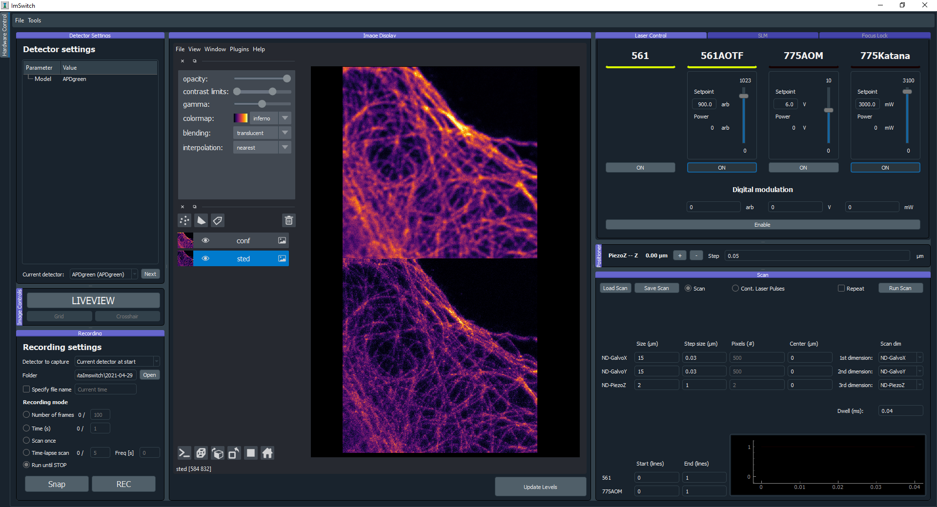
The main, and only, module for this use case is used to control all the hardware, screen the sample with widefield, acquiring the images, and inspecting them with the visualization tools. We have provided a more detailed explanation of the GUI here. To record a confocal image, the user sets the scan parameters that they want for each scan axis (length, pixel size, center position), the pixel dwell time, sets the laser powers they want to use, set the TTL start to 0 and end to 1 (units is lines) for the excitation laser they want to use, and runs the scan. The view of the detectors not in use can be hidden in the visualization tool. The scanning module will build the scanning curves, laser modulation curves, create those tasks in the Nidaq, and start them. The raw data is displayed in the liveview, where the image is updated line-by-line during the acquisition. For recording a STED image the procedure is much the same, with the addition that the use turns on the STED laser in the laser module, and sets the corresponding TTL start and end to the same values, and runs the scan. Before this the SLM has to be configured in order to create a desired depletion pattern, where for using a donut and tophat there are helpful tools in the SLM module to align the mask and the aberration correction that will be specific to each setup.
Previous to any image acquisition, while using either a repeating fast confocal scan or a widefield image, the sample has to be set in focus, and the focus lock can then be used to lock the sample in the focal plane. The focus lock acts independent from the image acquisition and can be continuously turned on for as long as wanted.
The user can choose to save the acquired image to a desired folder and with a desired name by using the Snap button in the recording widget. It will be saved in hdf5 format, and will include all user-defined parameters from the GUI as metadata. Functionality to reload metadata parameters from a previously saved hdf5 file can be found in the toolbar, for easy and precise recreation of a previous experiment. Previously recorded images in tiff format can also be loaded in the visualization module in order to be directly compared with the last recorded image or each other.
GUI after having acquired a confocal and a STED image:
CoolLED control through USB and TTLs using a NIDAQ
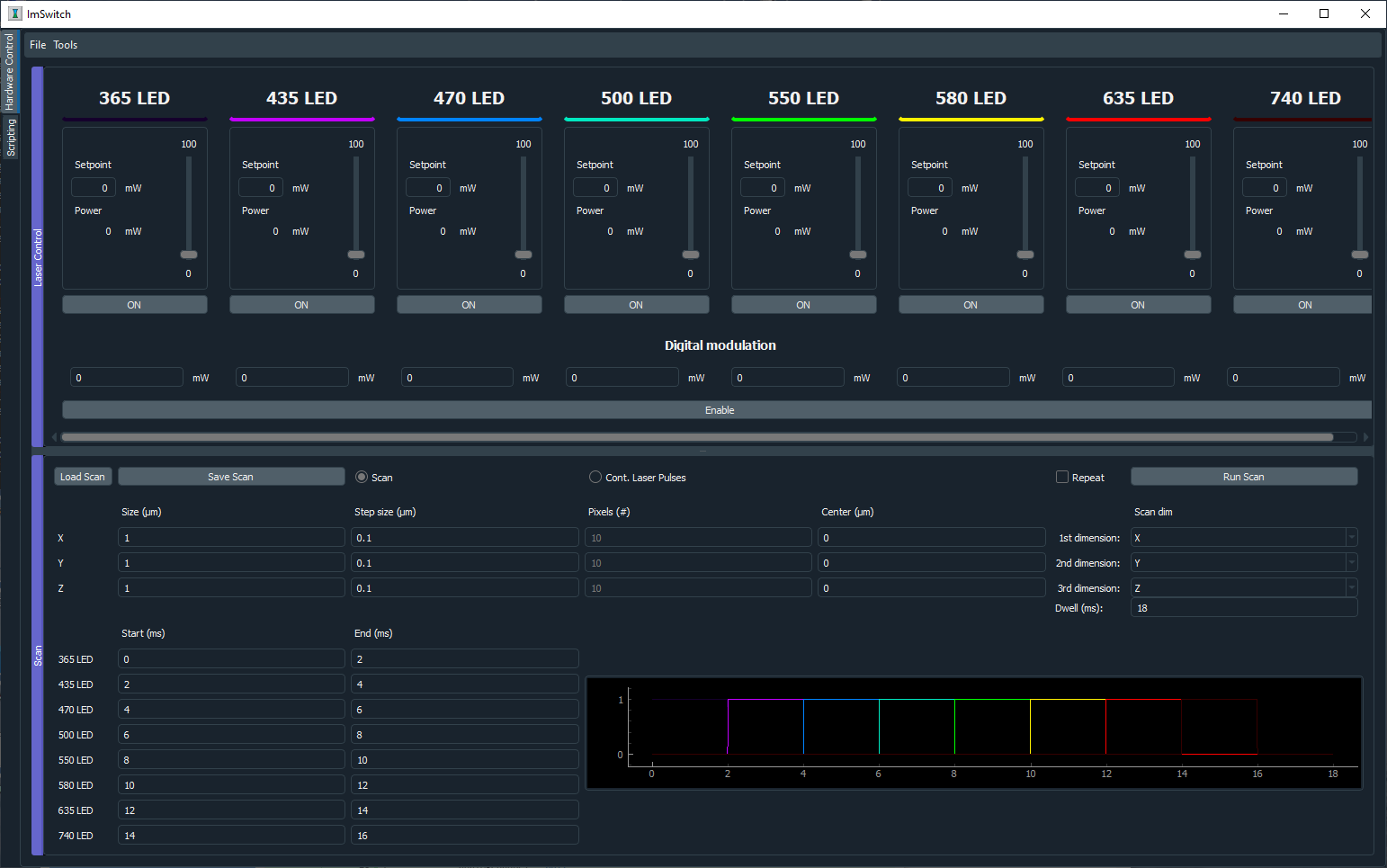
We got a CoolLED (https://www.coolled.com/) in the lab and decided to try ImSwitch out in a setting where we want to control the 8 lasers of the device, both by doing it manually using the sliders and buttons (using a USB port and RS232 communication protocol), but also being able to design and perform a sequence of TTLs and a X-Y-Z Stage controlled by a National Instruments card. This use case could be combined with the Napari viewer and a camera, or a point scanning system, or any of the other widgets explained in the other Use Cases.
All the lasers are listed in the JSON file example_coolLED.json, located at /imswitch/_data/user_defaults/imcontrol_setups/example_coolLED.json, by specifying:
Digital line of each laser in the NIDAQ.
Wavelength and range (0 to 100).
Channel name (A-H), each corresponding to the laser.
The Positioners define the stage axis with the settings, such as:
Analog channel of the NIDAQ.
Conversion factors.
Min and Max voltages.
Axis (X, Y, or Z).
Then, the CoolLEDLaserManager will communicate with the RS232Manager for sending the intensity and on/off commands. The parameters of the RS232Manager are the typical ones
of a RS232 connection, such as:
Port (Usually COMx).
Encoding (ascii).
Baudrate (57600).
ByteSize (8)
Parity (None)
Stop bits (1)
The pulses will be directly handled by the National Instruments card and our TTLDesigner.